8
What makes those methods better?
Disclaimer, I'm at a sortof "advanced hobbyist" level of cad. My understanding of the topological naming problem in general is that it exists in all cad because it is a sortof byproduct of how computers keep track of data about 3 dimensional objects. If you make a cube, all the sides need to have an identifier associated with them. If you put a hole in that cube, you now have more identifiers and have to decide what ordering makes sense. It sounds easy to work around with a cube but when models get really complex it's not so easy, especially when you change something way back at the beginning which creates more or less faces in the middle of the list somewhere.
Freecad isn't making the topological naming problem "go away". They are creating (or rather merging, it's been around a long time) an algorithm that makes a better guess at what the order should be, rather than sticking new faces in the list and reordering without any consideration of what happened after that face was created. This is, as far as I understand, also how other CAD packages do it, and you can still back yourself into a topological naming problem if you try hard enough (or don't try at all I guess) in both freecad with the new changes applied, and in other CAD packages.
So "best practice" is to be smart about the attachment of your geometry thinking about how things might change in the future, rather than clicking the closest face whenever you need a sketch plane. In reality modern proprietary cad is so good at guessing and maintaining consistency that it doesn't matter unless your model is horrendously complex and whoever made it didn't pay any attention to laying out the base sketches in an organized way.
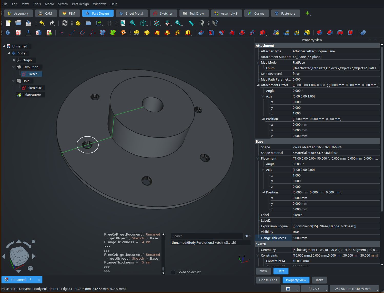
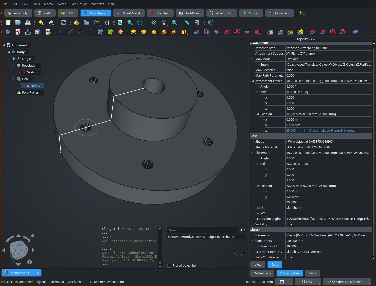
For example if you make a flange but you're not quite sure about the thickness, base the sketch for say, the holes, on the parallel origin and offset it by the height of the pad or the length of the sketched geometry. Or use a spreadsheet or variableset for the value of both the thing that you define the thickness with, and the offset from the origin plane. That way if the value changes, nothing will break.
I made a test model but it isn't something that shows up well in a single screenshot unfortunately. See the "Flange Thickness" and z offset parameters in the property view. I used that for the flange dimensions, and the hole sketch offset.
The SQLite database is encrypted, though there was a period of time where it wasn't I think which may persist if your DB is older, but the key is stored right next to it on the filesystem. Signal desktop doesn't use your keyring or any of the other available methods to unlock it's database which is why you don't have to enter anything when starting the application, and why you can move it between machines by simply copying the
.config/Signaldir. So while they are "encrypted", it's effectively clear text if you have access to the directory the database is stored in.