nilclass

joined 1 year ago
[–] [email protected] 2 points 18 hours ago (1 children)

I'm not sure I understand what you are trying to do... do you want to build a radio? Or are all your signals in the audio range?

Anyway:

Regarding Gilbert cells, the two popular chips are MC1496 and SA631. The 631 comes with a built-in oscillator, so it's quite handy. Unfortunately both are hard to come by these days.

[–] [email protected] 35 points 4 days ago (7 children)

Does this mean jd vance is a centipede?

[–] [email protected] 3 points 1 week ago

πŸ—‘οΈπŸ’ͺ

[–] [email protected] 18 points 1 week ago

Sounds great, except i think this whole thing is about some punching game.. Not sure though, i'm not a sports person

[–] [email protected] 35 points 1 week ago (1 children)

Heresy! Australia will always be a planet.

[–] [email protected] 1 points 2 weeks ago

Damn, i was hoping for them to make it slower!

[–] [email protected] 3 points 2 weeks ago

I can only find pictures of 6-lobed Gamebit screws

[–] [email protected] 5 points 2 weeks ago (1 children)

thanks, this might be just the comment I needed! Some of the screws are sunk into a very deep hole (~60mm), so it would be tough to cut a slot into those. But i'll give it a try on one of the more exposed screws, just to see if that gets me anywhere.

[–] [email protected] 6 points 2 weeks ago

true, looking at second pic it's very hard to make out. I tried to capture it on the first picture, but it's not that good

[–] [email protected] 5 points 2 weeks ago

yeah, it is inverted (or "external" torx according to your link). They also made sure to sink the screws into a whole where no pliars will fit...

55
What kind of screw is this? (discuss.tchncs.de)
submitted 2 weeks ago* (last edited 2 weeks ago) by [email protected] to c/[email protected]
 

EDIT: I believe I found the answer, it's something turned by this: https://ctatools.com/products/5065

Found some trash on the street that i'd like to take apart, but this screw is in my way.

It's like a hex bolt, but with 5 sides, and rounded (a bit like flower petals).

Here's another picture from the top:

I tried turning it with various tools (hard to get pliars in unfortunately), no success so far. The material is very soft, which doesn't help..

53
help (discuss.tchncs.de)
 

I can't recall a time when I wasn't lost in the inner solar system. Currently I'm stuck on the third dot - how do I proceed?

Alt


The picture shows today's XKCD comic.

Transcript:

[A grayed-out sentence in the Times New Roman font reads "Optimistic aliens measure space typographically". The "O" in "Optimistic" is dark black and indicated as representing the Sun (not to scale). The dots of the letters "i" in the sentence are similarly dark black. The dot in the first "i" in "Optimistic" is indicated as representing Mercury; the dot in the second "i" represents Venus; the dot in the third "i" represents Earth. The dot in the "i" in "aliens" is indicated as representing Mars. The dot in the "i" in "typographically" is indicated as representing Jupiter. A measurement bar indicates that the distance between the "O" and the third "i" in "Optimistic" is equivalent to 1 AU (astronomical unit).]

[Caption below the panel:] 
Space tip: if you're ever lost in the inner Solar System, you can just type out the phrase "Optimistic aliens measure space typographically" in Times New Roman and use the dots as a map.

16
submitted 1 year ago* (last edited 1 year ago) by [email protected] to c/[email protected]
 

I am powering a 5V microcontroller (arduino clone, atmega328p) using a 9V block and a buck converter. Now I want to let the microcontroller occasionally measure the battery voltage, so I can get an idea of how full it is.

My first idea was to use a simple voltage divider:

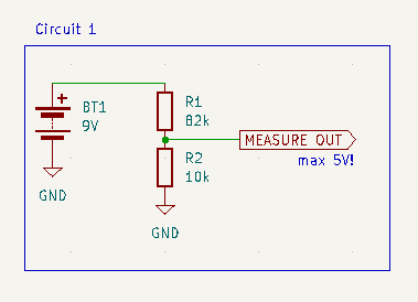
I've chosen the resistor values so that:

  • the voltage at the measure output is < 1.1V, to be able to use the 1.1V internal reference of the atmega's ADC
  • R1 || R2 < 10kΩ, since the atmega datasheet says "The ADC is optimized for analog signals with an output impedance of approximately 10 kΩ or less"

This is great and all, but what bothers me is that this circuit will constantly draw ~100Β΅A from the battery.

So, my next thought was to add a mosfet to the divider, to switch it on only while measuring:

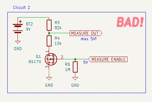
This is obviously bad, because now when the mosfet is off, the ADC input sees the whole battery voltage.

To address that issue, I've added a second mosfet into the measure path:

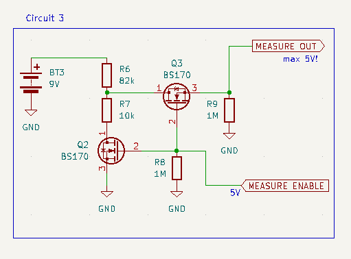
This works, and it does not draw any current, except while measuring.

However, it's quite a few parts. So I'm curious if anyone has an idea how to do this with just a single mosfet. It seems to me like it should be possible, but I haven't figured out how.

Oh, and if I'm doing something stupid here, please tell me :)


I have a whole bunch of them. They are possibly a bit older (70s, 80s) judging by other contents of the junk box they are from.

There are no labels of any kind, but on the top they have stripes that look hand painted.

For at least some of them the resistance roughly corresponds to the color code.

So, I'm just curious why I can't find anything about these on the internet.


Does anybody know a source for the IARU bandplan (such as this) in a machine-readable form? Or something similar?

I'm mainly interested in the frequency ranges for each mode, and the maximum bandwidth. Typical channel spacing would also be nice info.

view more: next β€Ί