6
[USA] Walgreens: six free 5x7 photo cards. Use code 6CARDSFREE . Exp 5 October
(photo.walgreens.com)
commercial appliances didn’t take any stand-by measures to avoid “keeping the wires warm”
Generally speaking, the amount of standby current attributable to the capacitors has historically paled in comparison to the much higher standby current of the active electronics therein. The One Watt Initiative is one such program that shed light on "vampire draw" and posed a tangible target for what standby power draw for an appliance should look like: 1 Watt.
A rather infamous example of profligate standby power was TV set-top boxes, rented from the satellite or cable TV company, at some 35 Watts. Because these weren't owned by customers, so-called free-market principles couldn't apply and consumers couldn't "vote with their feet" for less power-hungry set-top boxes. And the satellite/cable TV companies didn't care, since they weren't the ones paying for the electricity to keep those boxes powered. Hence, a perverse scenario where power was being actively wasted.
It took both carrots (eg EnergyStar labels) and sticks (eg EU and California legislation) to make changes to this sordid situation. But to answer your question in the modern day, where standby current mostly is now kept around 1 Watt or lower, it all boils down to design tradeoffs.
For most consumer products, a physical power-switch has gone the way of the dodo. The demand is for products which can turn "off" but can start up again at a moment's notice. Excellent electronics design could achieve low-power consumption in the milliwatts, but this often entails an entirely separate circuit and supply which is used to wake up the main circuit of the appliance. That's extra parts and thus more that can go wrong and cause warranty claims. This is really only pursued if power consumption is paramount, such as for battery-powered devices. And even with all that effort, the power draw will never be zero.
So instead, the more common approach is to reuse the existing supply and circuitry, but try to optimize it when not in active operation. That means accepting that the power supply circuitry will have some amount of always-on draw, and that the total appliance will have a standby power draw which is deemed acceptable.
I would also be remiss if I didn't mention the EU Directives since 2013 which mandate particular power-factor targets, which for most non-motor appliances can only be achieved with active components, ie Active Power Factor Correction (Active PFC). While not strictly addressing standby power, this would be an example of a measure undertaken to avoid the heating caused by apparent power, both locally and through the grid.
How were you measuring the current in the power cable? Is this with a Kill-o-watt device or perhaps with a clamp meter and a line splitter?
As for why there is a capacitor across the mains input, a switching DC power supply like an ATX PSU draws current in a fairly jagged fashion. So to stabilize the input voltage, as well as preventing the switching noise from propagating through the mains and radiating everywhere, some capacitors are placed across the AC lines. This is a large oversimplification, though, as the type and values of these capacitors are the subject of careful design.
Since a capacitor charges and discharges based on the voltage across it, and because AC power changes voltage "polarity" at 50 or 60 Hz, the flow of charge into and out of the capacitor will be measurable as a small current.
Your choice of measuring instrument will affect how precisely you can measure this apparent power, which will in-turn affect how your instrument reports the power factor. It can also be that the current in question also includes some of the standby current for keeping the PSU's logic ICs in a ready state, for when the computer starts up. So that would also explain why the power factor isn't exactly zero.
An outside description of Squatober: https://www.garagegymreviews.com/squatober
I like the concept of a month-long squat fitness challenge but I personally don't jive with the notion of having to follow two Instagram accounts daily to get the next day's program description. My life requires a bit more advance notice than that.
Agreed, it's a very bad design. If your school speed limit covers most of the daylight hours on weekdays, is the implicit suggestion that it's fine to drive faster on weekends and during nighttime? The street should be rebuilt to enforce the desired speed limits, not with paint or signs.
Oh, we're talking about the letters on the glass. My bad lol
You may want to include a photo of the piece, ideally many photos from various angles.
But to be frank, unless you find someone within a max 1 hour's travel distance, it's not likely someone will be found who is also willing to take on this project. Wood furniture is, for all its pros and cons, heavy.
A few months ago, my library gained a copy of Cybersecurity For Small Networks by Seth Enoka, published by No Starch Press in 2022. So I figured I'd have a look and see if it it included modern best-practices for networks.
It was alright, in that it's a decent how-to guide for a novice to set up sensible, minimum network fortifications. But it only includes an overview of how those fortifications work, without going into the additional depth needed to fine-tune or optimize them for specific environments. So if the reader has zero experience with network security, it's a worthwhile read. But if you've already been operating a network with defenses for a while, there's not much to gain from this particular text.
Also, the author suggests that IPv6 should be disabled, which is a terrible idea. Modern best-practice is not to pretend IPv6 doesn't exist, but to assure that firewalls and other defenses are configured to handle this traffic. There's a vast difference between "administratively reject IPv6 traffic in/out of the WAN" and "disable IPv6 on all devices and pray no one ever connects an IPv6-enabled device".
You might have a look at other books available from No Starch Press, though.
I lost it when coming across this commit: https://github.com/WinampDesktop/winamp/commit/67c68e6dc24f36b266427034d016fb86ef4d486c
Other commenters addressed some of the possible clearance issues, where a wider tire might interfere with the frame. But it seems to me that the discussion on tire/rim compatibility can be fleshed out.
To lay some background, a bicycle tire is essentially mostly a hollow rubber donut, but with the inward-facing "donut hole" walls supported instead by a pair of co-axial steel hoops, known as the beads. Thus, the beads define the inner diameter of the tire. When a tire is inflated, the air pressure will cause expansion in all directions. The tire's beads and walls (ie casing) will hold their shape, but the air pressure will try to push the two beads apart. This is where the rim walls come into play: the rim walls prevent the beads from widening apart. With the air pressure fully contained in all directions, the wheel assembly can now support impressive loads relative to the weight of the rubber and metal.

So for a bicycle rim and bicycle tire to be compatible, the two most basic criteria must be met:
The first criteria is a strict match, so that's easy to check. But the second criteria has some allowance for different tire widths on a given rim, or different rims for a given tire width. We can now look at what rims you have, and whether they're compatible with your preferred tires.
It looks like your rims are Weinmann DP18 rims, which have a trade diameter of 700C and the narrowest part of the rim walls are 12.40 mm apart. I say "trade diameter" because no part of the rim actually measures 700 mm. Instead, rim/tire compatibility can only reliably be calculated using the ISO/ETRTO measurements, which are a pair of numbers that directly answer the two compatibility criteria from earlier.
The first number in the ETRTO system is the inner rim width, and the second number is the bead seat diameter, both in millimeters. So your rims would be universally identified as 12-622 or 13-622, since 622 mm is the actual circumference if you put a tape measure around the rim. The first number can be 12 or 13 because 12.40 mm could round up or down. Sub-mm precision does not substantially matter here.
Now we can look at your desired tires, which have a trade designation of 700x38c but they also give the ETRTO measurement of 40-622. Unlike rims, the trade designation does actually convey some measurable dimension of the tire, but these are irrelevant for tire/rim compatibility. See the spoiler below for more.
fuller explanation of tire trade designations
In this case, 700 mm is the approximate outer diameter of the tire, which is only useful if:
Also, 38 mm is the approximate width of the tire when inflated. This is allowed to differ from the ETRTO width, since balloon tires on MTB bikes can be substantially wider than the rim, and road bike tires can be narrower than the rim. This width is mostly only useful to check the clearance between your forks, although it's also useful to know if you're riding near streetcar tracks.
Narrow tires can get caught in the groove along the tracks, whereas wider tires can glide over them. A skilled rider can navigate tracks with any tire width, but it's still a hazard that needs to be identified and negotiated.
So we now know the rim is 13-622 and the desired tire is 40-622. Checking the first criteria, we see that the diameters (622 mm) are a perfect match. Great! But for the width, because there is an allowable range, we need to consult a width compatibility table. Some tire manufacturers will be more permissive while others are more conservative with their published tables. And there are often separate tables for road bikes versus MTB. But these tables won't vary too substantially in their recommendations. Here are two tables, one from Continental and another from WTB.


Both tables indicate that for the 13 mm rim width column, the recommended tire widths are 18-27 mm (Continental) or 23-25 mm (WTB). Your preferred tire has an ETRTO width of 40 mm, which is way too far outside of the recommendations. So no, it doesn't look like this tire can be safely mounted on your existing rims.
But what would happen if you tried it anyway? We can see from the table that a 40 mm tire should normally be mounted on a rim with widths 17-27 mm. So 13 mm would mean the tire beads will be squeezed closer together than designed. This means more of the tire's tread will be wrapped up on the sides rather than facing down at the road. This also reduces the contact patch where the tire meets the road.
Finally, a wide tire on a narrow rim exerts more leverage that could pull the tire up and off the rim. This would happen if the bike is loaded sideways, such as leaning the bike to one side while riding straight, or when the rider leans further than the bike in a curve. The recommended values take these conditions into account, so exceeding the recommendations might still work day-to-day but fail during rarer conditions.
My recommendation is to pursue a new set of rims that can support tire widths suitable for your new environment. As the tables show, 13 mm rims are very limiting, but 17 mm rims are very permissive. Indeed, a 17 mm rim would actually allow you to mount your preferred tires (ETRTO 40-622) and possibly your existing tires (ETRTO 25-622 ?) too, if you wanted to.
I wish you good luck in your endeavors!
This reminds me of the time I happened to be at a warehouse where an industrial motor control panel was being decommissioned. In the center of the panel is a large breaker, which was dutifully opened (ie powered off) before work commenced. But bizarrely, someone in the past managed to tap power from the supply-side of the breaker for some sort of monitoring sensor inside the panel. So when that circuit was cut through, there was a loud bang and the overhead lights went out.
No one was injured, although everyone was jumpy from the inadvertent light-and-sound spectacle. And a set of cutters gained a 12 AWG-sized (approx 4 mm^2) hole.
I may have misremembered some details, but my takeaway as a non-electrician was to 1) never assume a breaker handle at face value, and 2) don't assume the prior person made sane choices.
This is a good question and I don't really know how this device would affect drafting and related manoeuvres. But if I had to guess, drafting behind a lead cyclist should still be beneficial, but the "zones" where it works might change.
So for example, the optimal distance lee-ward of a lead cyclist might become shorter or longer. Longer could mean more space to vie for that position directly behind the lead. But shorter might mean it's impossible to draft without crashing into the lead.
Side-to-side drafting distances might also be affected, like how birds travel in a vee-shape. Maybe the vee would become wider? That might not be beneficial, though, if it's so wide that it's impossible to stay on the racecourse.
TL;DR: I have no idea, and aerodynamics are hard. That's why I'm intrigued by the field.
My understanding is that it has to do with form drag -- aka pressure drag -- which results in vortices forming in the "separation region" directly behind an airfoil. Or in this case, a rider. Essentially, the swirling of air behind the rider is turbulent -- which is why a hoodie might flop all over the place -- and that causes energy to be lost.
This video on Nebula (and YT as well) describes pressure drag at about the 02m30s mark for a sphere. But this graphic from Skybrary also shows the problem:
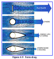
By providing a smooth surface for air to "cling" to, where it would otherwise form vortices in the separation region, should reduce form drag, although it will cause additional induced drag (aka friction with the new surface). But induced drag scales with speed and at cycling speeds, that's less a problem than it would be at airplane speeds.
A related drag-reducing device has been used for semi-truck trailers, and those have really been proven to reduce fuel consumption. Although the Wikipedia article does not describe in detail the aerodynamic principles at play.
cross-posted from: https://sh.itjust.works/post/22165919
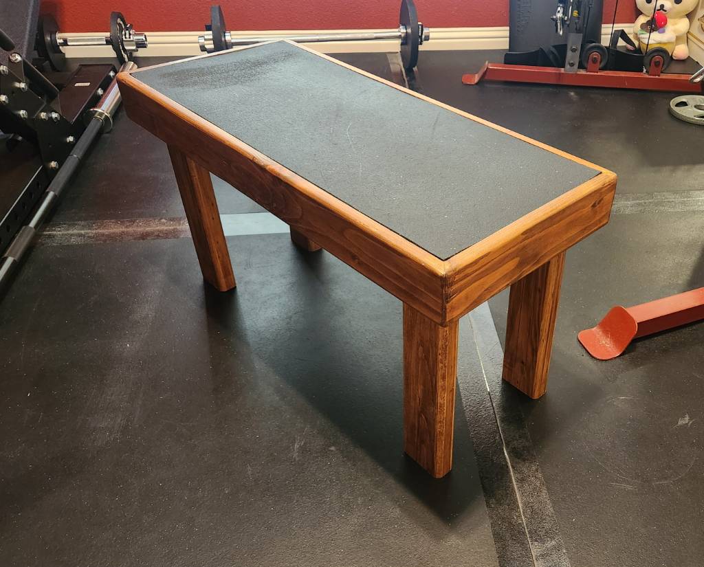
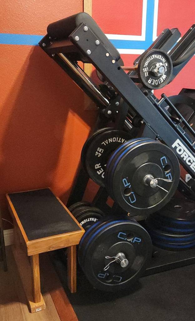
This entry of mine will not match the customary craftsmanship found in this community, but seeing as this was formerly a pile of miscellaneous, warped scrap 2x4 segments recovered from old pallets, I think I've made a reasonable show of things.
This bench is for my homegym, designed to be stood upon, which is why there's a rubber mat inlaid on the surface, a leftover of the gym floor. My design criteria called for even the edge of the top surface to support weight, so the main "box" of the bench uses 2x4 segments mitered (badly) together at 45 degrees, held together with wood glue.
I then routed the inner edge to support a 1/2" plywood sheet, which is screwed into the box. And then the rubber mat is glued down to the sheet, so there are no visible screws.
Finally, the legs are also 2x4 segments, cut so the bench sits 43 cm (~17 inch) from the floor; this is only coincidentally similar to the IPF weightlifting bench standards. I used screws instead of glue, just in case the legs needed to be shortened later.
All edges were rounded over with a 1/2" bit, as the bench is expected to be picked up and moved frequently. And everything stained in cherry and clear-coated.
Some of the annoyances from using scrap included:
- Stripping old paint off. Awful chemicals, awful scrubbing, awful disposal.
- Sanding away twists along the 2x4 segments
- Filling nail holes or arranging them so they don't draw attention
- My lack of experience with clamping and gluing wood that's not dimensionally consistent
If I were to do this again, I'd figure out a way to reduce the amount of routing needed for the inner edge, since I essentially removed 0.75 inch by 1.5 inch of material all around the edge. This took forever, and perhaps a CNC machine would have simplified things, in addition to squaring and planing the surfaces before mitering.
This entry of mine will not match the customary craftsmanship found in this community, but seeing as this was formerly a pile of miscellaneous, warped scrap 2x4 segments recovered from old pallets, I think I've made a reasonable show of things.
This bench is for my homegym, designed to be stood upon, which is why there's a rubber mat inlaid on the surface, a leftover of the gym floor. My design criteria called for even the edge of the top surface to support weight, so the main "box" of the bench uses 2x4 segments mitered (badly) together at 45 degrees, held together with wood glue.
I then routed the inner edge to support a 1/2" plywood sheet, which is screwed into the box. And then the rubber mat is glued down to the sheet, so there are no visible screws.
Finally, the legs are also 2x4 segments, cut so the bench sits 43 cm (~17 inch) from the floor; this is only coincidentally similar to the IPF weightlifting bench standards. I used screws instead of glue, just in case the legs needed to be shortened later.
All edges were rounded over with a 1/2" bit, as the bench is expected to be picked up and moved frequently. And everything stained in cherry and clear-coated.
Some of the annoyances from using scrap included:

If I were to do this again, I'd figure out a way to reduce the amount of routing needed for the inner edge, since I essentially removed 0.75 inch by 1.5 inch of material all around the edge. This took forever, and perhaps a CNC machine would have simplified things, in addition to squaring and planing the surfaces before mitering.
Looking at the images you've attached, this appears to be an 8 ft wide by 6 ft tall fence. That's a good amount of weight in just the wood, and there isn't any part of the design that diagonally braces the frame, except the steel cable... which tore from its mounts.
My layman's view is that you absolutely need diagonal wood elements, which should only be installed after unloading the fence, either by removing the boards or by propping up the wheel-end so the frame returns to being squared. If the wheel interferes with this, remove it for the time being.
But I think you'd still need the steel cable, and if that has broken from its originally designed mooring, then this gate is already compromised. You may have to start over with a new Adjust-A-Gate kit or repair the current one so the cable will mount to the steel parts, rather than the wood.
I would say to rectify the diagonal supports first, before doing anything with the hinges, since if the hinges were actually the root problem, this gate would have already fallen over. That said, it seems to me that such a wide gate might have called for more substantial hinges.
The other commenter's suggestion to consider a pair of less-wide gates is also sound, if the goal is a minimal-fuss gate that will last at least a decade of additional sagging and weather.